Types of Transistor Audio Amplifier Circuits
A transistor audio amplifier circuit is a circuit that is used to amplify audio signals for use in radios, home audio systems, and other audio applications. This is done by using one or more transistors to increase the power of an incoming signal. There are two main types of transistor amplifiers: the bipolar junction transistor (BJT) type and the field-effect transistor (FET) type.
The BJT type can be further divided into the common-emitter, common-base, and common-collector configurations, each of which offers different levels of gain and efficiency. Among the configurations, the common-emitter amplifier is the most widely used because it provides high voltage gain and good current gain. The common-collector amplifier, also known as an emitter follower, has a voltage gain of less than one but can provide a high current gain. This makes it useful for impedance matching between different parts of a circuit.
The FET type of amplifier, on the other hand, is commonly used in high-impedance, low-power applications. Like the BJT, it can be configured in three different ways: common source, common gate, and common drain. The common-source FET amplifier is most often used because it provides high voltage gain and good input and output impedance matching, while the common-drain amplifier is used for impedance transformation. The common-gate amplifier, finally, is used in applications where a high input impedance is required.
Aside from the BJT and FET types, there are two amplifier classes for power amplifiers, namely Class A and Class B. Class A amplifiers are known for linear amplification and low-distortion, but they are less efficient and generate more heat. They are used in high-fidelity audio systems. Class B amplifiers, on the other hand, use one transistor for the positive half cycle and another for the negative. This is more efficient than Class A but generates more distortion.
Classes AB, C, D, E, and F are also used in audio applications. Class AB is a combination of Class A and Class B. It conducts more than half but less than 360 degrees of the input signal. It has low crossover distortion and is commonly used for audio amplifiers.
Function and features
Transistor audio amplifier circuits are designed to take the relatively low power output from a signal, like that produced by a turntable stylus reading a record groove, and make it powerful enough to drive a loudspeaker. Hence, the primary function of a transistor audio amplifier is to boost the input signal power to drive speakers while maintaining an accurate reproduction of the input signal. Here are some key features of a basic audio amplifier:
- Gain Control: The amplifier has a variable gain control to adjust how much the input signal is amplified. This feature allows the user to set the amplifier to the desired volume level and adjust sensitivity to the input signal.
- Output Power: It is the power an amplifier can deliver to a load or a loudspeaker. It is usually measured in watts. The amplifier's output power determines how loud a speaker can be driven and how large a room it can fill. A higher output power allows the amplifier to drive larger speakers and fill bigger rooms.
- Signal-to-Noise Ratio (SNR): This is a measure of the amount of noise present in the amplifier's output signal compared to the actual audio signal. A higher signal-to-noise ratio means a cleaner, less noisy sound reproduction. Hence, amplifiers with low noise and high signal-to-noise ratios are preferred for high-fidelity audio systems where accurate sound reproduction is critical.
- Bandwidth: This is the range of frequencies an amplifier can handle. The bandwidth of an audio amplifier typically extends from a lower cutoff frequency (the lowest sound it can reproduce) to an upper cutoff frequency (the highest sound it can reproduce). The wider the bandwidth, the more accurate the sound reproduction will be.
- Harmonic Distortion: This refers to the alteration of the signal by the amplifier in the form of additional frequencies that were not in the original signal. Lower distortion levels are desirable for faithful music reproduction. The total harmonic distortion plus noise (THD+N) is a common measurement that indicates how much the amplifier deviates from the original signal.
Usage Scenarios of a Transistor Audio Amplifier Circuit
When it comes to the usage of a transistor amplifier circuit, they are very versatile and can be used in many different scenarios. Below are some of the common uses of transistor audio amplifier circuits:
- Home theaters: A home theater system is a common application of an audio amplifier circuit. The system comprises various components that include an amplifier that powers the speakers. A transistor amplifier circuit is ideal for home theater use as it can boost the audio signals produced by DVD players, music players, or streaming devices to make the sound more audible. The transistor amplifier also delivers a rich and detailed sound quality, which is a good listening experience.
- Public address systems: Public address systems are used to amplify sound in public spaces. Whether it is an airport or a stadium, a public address system uses a transistor amplifier circuit to magnify the sound produced by the microphone. The amplifier ensures that the sound reaches a large audience. It also ensures that the sound is clear and without distortion. The amplifier also has enough power output to cover a large space.
- Guitar and instrument amplifiers: Guitar amplifiers and other instrument amplifiers use transistor audio amplifier circuits to amplify the sound produced by the instrument. The amplifier also shapes the sound to make it more appealing to the ear. Guitar amplifiers help to modify the guitar's tone, and the amplifier also distorts the sound to create a desirable sound effect. Guitar amplifiers have preamp stages that allow guitar players to adjust the volume and tone of the guitar.
- Studio monitors: Studio monitors use transistor audio amplifier circuits to reproduce the sound from the audio source. The amplifier allows music producers to listen to music as they are producing it. Studio monitors are widely used in music production and audio engineering.
- Portable audio systems: Portable audio systems use transistor audio amplifier circuits to amplify the sound produced by smartphones, music players, or tablets. The portable audio system comprises a small amplifier and speakers that can be carried from one place to another. Bluetooth speakers are a common example of portable audio systems.
How to choose a transistor audio amplifier circuit
When purchasing a transistor audio amplifier circuit, one must consider the wattage, impedance, and number of channels.
Before purchasing a transistor audio amplifier circuit, consider the power output and how it will be used. The power output of an amplifier is measured in watts. A higher wattage amplifier will provide more power. If the amplifier is to be used in a space that is larger, a higher wattage is recommended. If the amp is to be used in a smaller space, a lower wattage will suffice. It is important to choose an amplifier circuit that is appropriate for the application.
When purchasing an amplifier circuit, evaluate the impedance of the speakers and ensure that it is compatible with the amplifier. The amplifier's output impedance should match the speakers' input impedance. This is to avoid damage to the equipment and to ensure optimal performance. The output impedance of an amplifier is the resistance the amplifier "sees" in the speakers or headphones it drives. Impedance is the measure of the resistance of a speaker to an alternating current (AC) that is produced by the amplifier. Measured in ohms, impedance is the speaker's resistance to AC, not a direct current (DC). Make sure that the amplifier can handle the lowest impedance of the speakers. Most amplifiers will have a minimum speaker impedance rating.
Determine how many channels are needed. A channel refers to the number of speakers that can be connected to the amplifier. For example, a two-channel amplifier can power two speakers. Many amplifiers come with two to eight channels. Choose an amplifier circuit that has the correct number of channels for the intended speaker setup.
Q&A
Q1: How do I choose a suitable audio amplifier circuit for a specific application?
A1: Determine the required power output, speaker impedance, and type of audio source to choose the right amplifier circuit that meets the application's needs.
Q2: What are the key components of a transistor audio amplifier circuit?
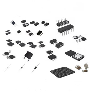
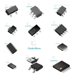
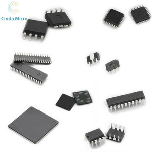
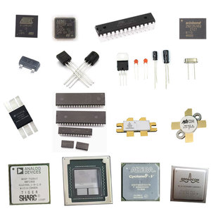
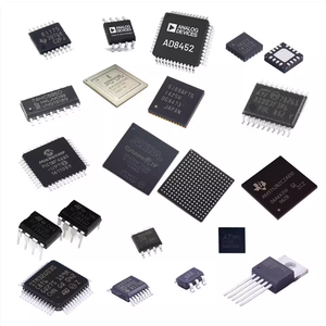
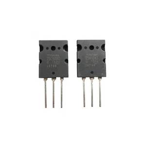
A2: The key components are transistors, resistors, capacitors, and the integrated circuit (IC) depending on the type of circuit design.
Q3: How does one test a transistor audio amplifier circuit?
A3: The circuit can be tested by connecting the audio input from a source like a smartphone or MP3 player and checking the output through a speaker. Ensure the sound is clear without distortion.
Q4: What are the safety precautions when working with a transistor audio amplifier circuit?
A4: Safety precautions include working in a well-ventilated area, avoiding contact with live wires, and using insulated tools to reduce the risk of electric shock. It's also important to handle heat-generating components carefully to prevent burns.
Q5: How can one troubleshoot common problems with a transistor audio amplifier circuit?
A5: To troubleshoot common problems, one should check for loose connections, damaged components, or incorrect wiring. Using a multimeter to test components for proper functioning is also helpful in identifying the cause of the issue. Additionally, referring to the circuit's schematic diagram can provide insights into the signal flow and component layout for more detailed troubleshooting.


 浙公网安备 33010002000092号
 浙B2-20120091-4