All categories
Featured selections
Trade Assurance
Buyer Central
Help Center
Get the app
Become a supplier
(5503 products available)

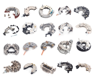


The testing regulator rectifier is vital in vehicle electrical systems. It ensures the right voltage and current, maintaining battery health. Several types of testing regulator rectifier are available, each with unique features and capabilities:
Single-Phase Rectifier
Single-phase rectifiers are the most basic type of regulator rectifier. They use one diode bridge to convert AC to DC voltage. This type is commonly used in small engines and low-power applications. Its main advantage is its simplicity and low cost. However, they are less efficient and have more voltage ripple than other types.
Three-Phase Rectifier
Three-phase rectifiers are more advanced than single-phase types. They use three diode bridges to convert AC to DC. This type is commonly used in larger engines and high-power applications. Three-phase rectifiers are more efficient and have smoother DC output. This feature makes them suitable for applications requiring high reliability and stability.
Active Rectifier
Active regulators are the most advanced type of testing regulator rectifier. They use controlled switches, like MOSFETs, to convert AC to DC. This type is used in high-performance applications, such as racing engines or high-speed electric motors. Active regulators offer the highest efficiency, lowest voltage ripple, and best dynamic response. However, they are more complex and expensive than other types.
Shunt Regulators
Shunt regulators are used to maintain a constant voltage level in a circuit. They divert excess current to maintain the desired voltage. This feature is useful in applications where voltage stability is critical, such as in sensitive electronic devices or precision instrumentation.
Series Regulators
Series regulators control output voltage by varying resistance in the circuit. They provide a stable voltage level but are less efficient than shunt regulators. Series regulators are often used in low-power applications or when precise voltage control is required.
Electrical Specifications
Voltage: The expected output voltage of the regulator is 12 VDC, while the output current can range between 10-40 A. Additionally, the power rating of the rectifier is about 480 W.
Current Ripple: The allowable current ripple on the output is about 10%, while the load regulation and line regulation are 5% and 2% respectively.
Efficiency: The overall efficiency of the regulator rectifier is 80%. Also, it has a power factor of 0.9.
Protection: The regulator-rectifier is protected against over-voltage, short-circuit, over-current, and thermal overload. It also has a surge immunity of 1,000 V and a lightning immunity of 1000 V.
Electromagnetic Compatibility: The device complies with the emission standards and the immunity standards.
Physical Specifications
Size: The length, width, and height of the testing regulator rectifier are 300 mm, 200 mm, and 100 mm respectively. Also, the weight is about 5 kg.
Environmental Conditions: The device can operate at a temperature range of between 0 °C to 50 °C. Also, it can function at a humidity of about 10% to 90%. In addition, the altitude of the device can reach 2000 m.
Mounting: The testing regulator rectifier can be mounted on a table or rack. It can also be mounted in a 19-inch rack.
Testing Specifications
Regulator-rectifier regulator voltage: This is the voltage level that is maintained consistently during the tests. The expected regulator voltage during the tests is 13.8 VDC, while the rectifier output voltage is 12 VDC.
Rectifier power: The regulator rectifier power is about 480 W, while its ripple voltage is not to be more than 100 mV. Also, the noise level is not to be more than 50 mV, while the regulator's transient response is about 100 ms.
The following are some maintenance requirements for the testing regulator rectifier.
Regular Inspection
It is important to check every component of the testing regulator rectifier system, including power supplies, control systems, and backup systems. The wires, connectors, and circuit boards should also be inspected to ensure they are in good condition and not damaged.
Cleaning
Regular cleaning of the testing regulator rectifier is a must, as this will prevent dust and debris from accumulating, which can lead to system failures. The exterior, as well as the interior components, should be cleaned using appropriate cleaning products.
Component Replacement
In the event of a failed component in any of the testing regulator rectifiers, it should be replaced immediately to avoid prolonging the downtime of the testing equipment. This will require maintaining a stock of spare components that are regularly checked to ensure they are in good working condition.
Software Updates
Regulator rectifier software needs to be updated regularly to ensure they are in good working condition. This will require checking the manufacturer's website regularly for updates and following the manufacturer's instructions to install the updates.
Calibration
The testing regulator rectifier needs to be calibrated regularly to ensure that its output is maintained at the required level. Follow the manufacturer's instructions for the calibration process, and use the appropriate calibration equipment.
The selection of a suitable regulator-rectifier for a specific use case or application requires a comprehensive understanding of various factors. Here are some of the key elements that need to be considered when choosing a testing regulator rectifier.
Understand the system voltage:
For any chosen regulator-rectifier, its voltage rating must correspond with that of the electric power system where it will be installed. This compatibility will guarantee that the current flow generated by the regulator-rectifier will not damage the electrical components within the system.
Consider the current capacity:
Different regulator-rectifiers have different current output ratings. Choose a testing regulator rectifier with a current rating that can sustain the load requirements of the electrical system. This will ensure that there is a constant current flow without overloading.
Understand the wave form:
Some regulator-rectifiers produce a sine wave current, while others generate a modified sine wave current. If the application requires specific current quality, choose a testing regulator-rectifier that meets the requirements.
Consider efficiency:
When selecting a testing regulator-rectifier, consider its efficiency rating. High-efficiency regulator-rectifiers result in less energy loss and heating. This means they regulate and rectify the current more reliably.
Quality and reliability:
Choose a testing regulator-rectifier from a reputable supplier with good quality and reliability. This ensures that it can maintain optimal performance and long service with less or no failure.
Special features:
Some regulator-rectifiers come with extra features such as surge protection, voltage stabilization, or monitoring capabilities. Depending on the needs of the electrical system, these additional features may be vital.
The voltage regulator rectifier is a very important component of the electric system of motorcycles. It is very important to ensure that the electric system is in good condition so that it can power the bike. If the bike has no power, then the chances are that the regulator rectifier is bad. Before replacing the regulator rectifier, DIYers need to carry out some tests to know if the previous one is really bad.
Doing this will help to prevent unnecessary change of parts. The test can be done using a multimeter, which is a common electrical testing tool used to measure voltage, current, and resistance. To perform a voltage test, set the multimeter to the appropriate voltage range for the motorcycle's electrical system (12V for most motorcycles). Start the bike and rev the engine slightly. Check the display on the multimeter to see if the voltage reading is stable. An unstable reading indicates a problem with the charging system. For a current test, set the multimeter to the appropriate current range. Connect the probes to the appropriate points in the circuit being tested (e.g., charging system or electrical component). Observe the current reading on the multimeter to ensure it matches the specifications. A significant deviation from the expected current indicates an issue with the electrical system. For a resistance test, set the multimeter to the resistance mode (ohms). Disconnect the battery or turn off the electrical system to avoid interference. Measure the resistance of relevant components (e.g., wires, connectors) in the electrical system. Compare the readings to the service manual's specifications. High resistance or open circuits can cause electrical problems.
After testing, if the rectifier is bad, then it is time to change it. Replacing a motorcycle regulator rectifier is a very easy task, and it can be done in no time. Before changing it, make sure to get the right tool for the job. Below are the tools and materials needed to replace a motorcycle regulator rectifier.
After getting the tools, the next step is to locate the old rectifier. In most cases, it can be found under the seat or behind the side panel. After locating it, remove the panel or seat to access the old rectifier. Before replacing the rectifier, make sure to compare the new one with the old one to be sure that it is a perfect match. After this, disconnect the battery by removing the negative (-) terminal first, followed by the positive (+) terminal. This step is very important to avoid short circuits and damage to the bike's electrical system during the replacement process.
Now, remove the bolts or screws holding the old regulator in place and carefully pull it out. At this point, it is safe to install the new regulator/rectifier. Connect the connectors (if applicable) and apply electrical grease to the pins to reduce friction. Reconnect the battery terminals, starting with the negative (-) terminal first, then the positive (+) terminal. Double-check all connections to ensure they are secure and properly seated. Start the bike and check if all the electrical components are working fine.
Q1: What is the function of the rectifier regulator?
A1: The rectifier regulator regulates the voltage and current of the motorcycle's electrical system. It converts the generated AC electricity into DC and maintains a steady output, regardless of the engine's RPM.
Q2: Can I upgrade to a more powerful regulator rectifier?
A2: Upgrading to a higher-capacity regulator rectifier is possible, but ensuring it matches the electrical requirements of the motorcycle is essential. An upgraded component should be compatible with the battery and overall electrical system to avoid damage.
Q3: What are the signs of a failing regulator rectifier?
A3: Common indicators of a faulty regulator rectifier include dimming lights, a flickering dashboard, difficulty starting the bike, and a weak battery. Other signs include an overly hot regulator rectifier or a burning smell. Visible damage on the component can also be a sign of failure.
Q4: What is the difference between a standard and a mosfet regulator rectifier?
A4: Standard regulator rectifiers use traditional technology to manage the voltage and current flow. In contrast, MOSFETs are faster and more efficient, resulting in less heat and better energy management. As a result, MOSFET regulator rectifiers offer improved performance and reliability.
Q5: Can I install a regulator rectifier myself?
A5: While it is possible to install the component without professional help, users must have the necessary skills, tools, and knowledge. It is essential to follow the manufacturer's instructions and ensure proper wiring to avoid damage or safety risks.