All categories
Featured selections
Trade Assurance
Buyer Central
Help Center
Get the app
Become a supplier
(440 products available)


Single-phase power factor correction uses a single-phase electrical supply to enhance the power factor, making energy utilization efficient. In contrast to three-phase systems that primarily find application in industrial setups, this system is more widely used in residential or small commercial setups. The correction mainly targets the reactive power component in the system, at times leading to substancial energy wastage.
PF Correction devices come in different types based on specifications and characteristics such as size, application type, and the amount of correction ability.
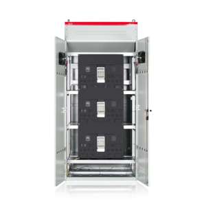
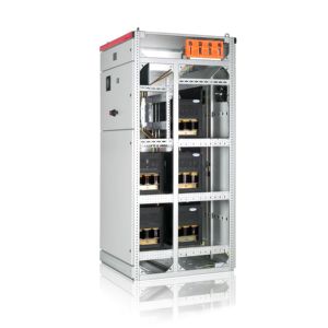
Capacitor Banks
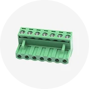
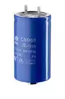
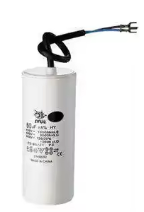
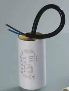
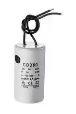
Capacitor banks are one of the most popular methods of power factor correction. Single-phase capacitor banks are composed of several capacitors grouped together to help increase the system's power factor by providing reactive power where needed. Small businesses running motors and inductive loads and domestic users frequently use these systems. Depending on the amount of reactive power that needs to be compensated, capacitor banks can be fixed or self-adjusting.
Supercapacitors
Although they are a new type of electrochemical energy storage device, supercapacitors are finding widespread application. Supercapacitors are more efficient than traditional capacitors because of their higher capacitance and longer charge-discharge cycles. Supercapacors temporarily store electrical energy to smooth fluctuations in power supply and enhance the power factor. This technology finds applications in renewable energy systems, electric vehicles, and backup power systems, where rapid energy fluctuations can be detrimental to the system.
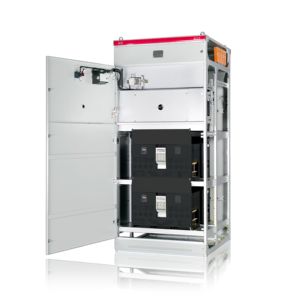
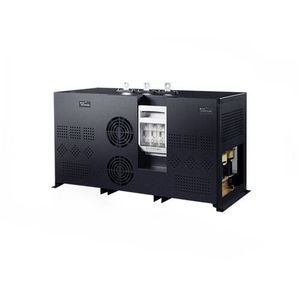
Active Power Factor Correction (APFC) Devices
These devices are called active correction devices. They monitor the system in real time and adjust the correction in an intelligent manner to help enhance the power factor. They are more versatile than conventional capacitors and can be utilized in a larger number of applications with varying reactive loads. These units are frequently used in electronic equipment, data centers, and industrial complexes.
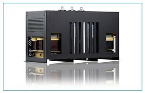
Shunt Capacitors
Shunt capacitors provide reactive power locally to electrical systems. Their installation can be at either the distribution network level or the customer premise level. The capacitors counter the inductive effects of equipment and thus minimize reactive power flow. Shunt capacitors are used mainly for voltage support and power factor correction in transmission and distribution networks.
Capacitor-Resistor-Filter (CRF) Circuits
A CRF circuit reduces harmonics and improves the power factor within a single device setup. It consists of a capacitor, resistor, and a phase-shifted inductor. By damping the resonances associated with certain frequencies, the CRF circuit minimizes harmonic distortion. That will also enhance the power factor, making efficient energy use.
Power factor correction is important for optimizing energy usage in electrical systems. A low power factor means poor efficiency, causing electrical devices to consume more energy than necessary. This leads to increased energy costs and sub-optimal performance. Correction improves efficiency by reducing energy waste, lowering bills, and improving system reliability.
Key specifications of PFC systems include:
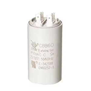
Capacitance: This refers to the ability of a capacitor to store electrical charge, and it is measured in farads. Higher capacitance means more reactive power compensation. Voltage rating: The maximum voltage a capacitor can withstand without failing. It must be higher than system voltages for safety. Frequency rating: The operational frequency range of the capacitor, typically 50-60Hz for standard systems.
Features and Components that help in PFC
Circuit Breakers: These protect capacitors from overloads, short circuits, and faults. At overcurrent or fault conditions, the circuit breaker trips and disconnects the capacitor to prevent damage.
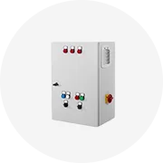
Control Panels: A control panel for a manual capacitor bank incorporates switches and meters to help monitor capacitance used and enable operability. Automatic banks have control systems that adjust capacitance depending on power factor in real-time.
Disconnect Switches: These switches manually disconnect capacitors from the system for maintenance while ensuring the bank is isolated from the power grid.
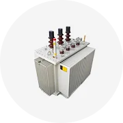
Transformers: Capacitor banks require step-up or step-down transformers to match bank voltage levels with electrical system ratings. This helps ensure safety and reliability.
Maintenance and upkeep of PFC devices
Power factor correction devices are very essential in electrical systems. Routine maintenance helps optimize performance, extend equipment lifespan, and minimize downtime. Maintenance includes regular inspections, operating conditions checks, and component replacements.
Periodic inspection is done in power factor correction devices by maintenance personnel. They inspect the devices for leaking oil, damaged insulation, corroded terminals, and worn components. Dust is removed, and repairs are carried out where necessary.
Maintenance of PFC devices involves replacing worn or damaged parts. This includes new capacitors, circuit breakers, control devices, and wiring. Preventative maintenance schedules specify replacement intervals based on component wear.
Devices are subjected to operational stress over prolonged periods, which subsequently affects capability and safety. Maintenance helps identify and resolve issues early before capacitors or other components suffer permanent damage.
Technology controls, such as power factor controllers, assist in maintaining optimal power factor values through corrective action. These devices are subjected to periodic maintenance, where factors such as calibration, which affects their functionality, are checked. Maintenance mainly involves replacing worn components and software updates.
Power factor correction devices affect electrical systems. Their maintenance involves disconnecting PFC devices from the electrical system. This helps during maintenance work. Maintenance work involves activities such as replacing faulty parts.
Various setups call for power factor correction. A domestic residential environment offers ideal power factor correction conditions, such as small commercial operations or off-grid single-phase power systems. The situation calls for factors such as system size, load type, and operational requirements to be considered when selecting appropriate correction methods.
Residential applications
A single-phase electrical system is easy to correct using simple PF correction methods, especially in a residential environment. These small-scale setups apply conventional capacitors or capacitor banks to increase the power factor and reduce the energy consumption bill. Voltage stability also improves with reduced reactive power on the system. In residential environments, household electrical appliances, air conditioning systems, and small electric motors frequently require power factor maintenance to ensure efficient operation and minimize energy wastage.
Renewable Energy Systems
Renewable energy, such as solar or wind, phases fluctuates and is often inconsistent. Supercapacitors help smooth this variability, storing excess energy when generation is high and releasing it when low. This improves reliability and power factor, making energy usage more efficient in renewable systems.
Industrial applications
In industrial plants powered by single-phase systems, PFC is very vital in ensuring reliability and efficiency. Active power factor correction devices are the ones that run mostly in this environment due to the variation in load types and operational modes. Electronic equipment that uses inductive loads, data centers, and electroplating facilities are just a few examples where active correction is applied. These devices also reduce harmonics, which would otherwise interfere with sensitive equipment.
Data Centers
Data centers employ active power factor correction (APFC) devices to enhance efficiency in distributed power systems. These devices optimize energy use by reducing wastage, cutting operational costs, and ensuring servers receive stable power for reliable performance.
Commercial Buildings
In commercial office buildings and retail spaces, PFC devices like capacitor banks reduce utility costs by minimizing reactive power. Saving energy lowers bills, improves efficiency, and allows more equipment to run without overloading circuits.
Utility Companies
Utilities also use PFC, such as shunt capacitors on transmission lines. By providing reactive power locally, these capacitors reduce the need for utilities to generate or purchase excess reactive power. This cuts costs and keeps systems efficient and reliable.
The choice of parameters is crucial for maximizing the benefits of PF Correction. Understanding different factors such as system size, load types, installation environment, and cost considerations helps make the right choice when it comes to correction method and system.
System Size
The electrical system size determines the power factor correction system size. Larger systems require more capacitance to provide sufficient reactive power. This ensures overall stability and efficiency. Accurate load analysis on these systems helps identify the corrective needs. That requires ensuring that the system has enough power factor correction. On the flip side, smaller systems need comparatively less capacitance. In this case, the solution could be a small-scale fixed capacitor or a supercapacitor.
Type of Load
Load types play a critical role in choosing PF Correction devices. Inductive loads like motors, compressors, air conditioning systems, and large electronic devices cause low power factors. These loads require capacitors to counter their inductive effects. This makes the power factor more efficient. Continuous versus intermittent load differentiation is equally important. Continuous loads require solutions that provide sustained correction. On the other hand, intermittent loads need devices that respond quickly to changing demands.
Installation Environment
The installation environment affects choosing PFC devices. This includes conditions like temperature, humidity, and space availability. Active power factor correction devices are ideal for environments where space is a constraint. They are more compact than traditional capacitor banks. On the other hand, outdoor installations require robust, weather-resistant equipment. This ensures durability in harsh conditions.
Budget
Cost considerations play an important role: initial capital investment versus long-term savings through reduced energy bills. Active PFC devices are more expensive upfront. However, their correction efficiency can lead to significant long-term savings. In such cases, a simple capacitive bank with fixed capacitors could suffice, as not only would it be cheaper to install, but it would also require very low operational costs.
Regulatory Requirements
Local regulations or utility company incentives impact PFC device selection. Some areas mandate power factor limits. Failing to comply results in penalties. Incentives like rebates for installing PFC equipment offset costs. Stay informed on regulations to avoid future compliance issues.
Power factor is the ratio of real power to apparent power in an electrical system. Real power is used to do work, while apparent power is the total power flowing in the system. A low power factor means inefficiency, wasting energy as reactive power. Conversely, a high power factor indicates efficiency, using energy effectively.
Low power factor in a system is caused mainly by the presence of inductive loads, such as electric motors, transformers, and relays. These devices draw reactive power, causing a phase shift between voltage and current. The current lagging behind voltage wastes energy and lowers efficiency.
A low power factor wastes energy, decreasing efficiency. Systems become overloaded, causing equipment heating, voltage drop, and trip risks, affecting reliability. Utilities penalize low power factors with higher costs, raising energy bills. Fewer capacity margins mean more strain on infrastructure, risking blackouts. Additionally, low power factor degrades power quality, leading to flickering lights and slow motor.
Reactive power demand on the electrical system can be reduced mainly through capacitors or synchronous machines. Capacitors, either fixed or variable, provide reactive power locally, aligning voltage and current to reduce phase difference. Synchronous machines supply or absorb reactive power as needed, increasing efficiency and stability.